Members
Members can be easily added in the graphical screen by drawing them. Choose in the function bar for  In this mode you can select 2 nodes between which the member is located.
- Choose the start node with the left mouse button. Select an existing node or place a new node.
- Choose the end node with the left mouse button. Select an existing node or place a new node.
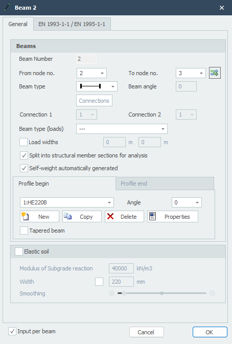
After selection of the 2nd node (the end node), the following dialog window appears.
Modifying a member
You can modify a member by clicking on the member with the left mouse button and then choosing properties with the right mouse button. Or even easier by double clicking on the member. The following dialog window opens:
Member number
The member number is automatically generated.
From node nr.
The number of the start node
To node nr.
The number of the end node
Member type
The member type specifies whether the member is hinged or moment-fixed connected to the node at that location.
| Symbol | Description |
|---|---|
 |
both sides 'rigidly' fixed (default) |
 |
start 'rigidly' fixed; end hinged |
 |
start hinged; end 'rigidly' fixed |
 |
both sides hinged |
 |
both sides 'rigidly' fixed TENSION only |
 |
start 'rigidly' fixed; end hinged TENSION only |
 |
start hinged; end 'rigidly' fixed TENSION only |
 |
both sides hinged TENSION only |
 |
both sides 'rigidly' fixed COMPRESSION only |
 |
start 'rigidly' fixed; end hinged COMPRESSION only |
 |
start hinged; end 'rigidly' fixed COMPRESSION only |
 |
both sides hinged COMPRESSION only |
 |
both sides 'spring' fixed |
 |
start 'spring' fixed; end hinged |
 |
start hinged; end 'spring' fixed |
 |
both sides hinged |

Specifically and only for spring member connections, the spring data must be specified. See Spring Connections
EN 1993-1-1
Specifically and only for verification according to Eurocode 3: NEN-EN 1993-1-1, data can be entered.
Buckling length The buckling length out of plane. The verification according to Eurocode 3: NEN-EN 1993-1-1 is based on a geometrically non-linear force distribution. This means that buckling of members in the plane of the frame is implicitly included. Internal equilibrium is determined iteratively for each load combination.
Buckling out of the plane of the frame will need to be assessed. By default, the buckling length out of plane is taken equal to the member length. In cases where this differs, a different buckling length can be entered per member.
Number of lateral supports Only relevant for lateral torsional buckling verification: The number of lateral supports is default 2. In cases where more than 2 lateral supports are applied, a different number can be entered per member.
Member group Specifically and only for lateral torsional buckling verification, a member group can be entered. XFrame2d automatically detects which members qualify. Only those members that are in line with the member being considered, are moment-fixed connected, and have the same profile are visible. You can check which members these are.
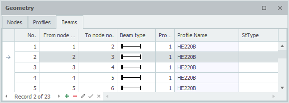
Member Table
Members can also be added and/or modified in the Members table at the bottom left. It doesn't matter. You can also switch between graphical input and tabular input at any time.