Node Displacements

Node displacements (forced node displacements) are added in a local coordinate system. See Design Arrangement.
The dialog box shown below is opened.
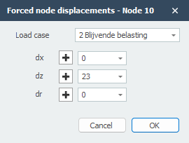
Load Case
Option for the load case. Here you can directly insert a new load case.
The node displacement will be inserted in the global coordinate system. When for a particular node, a local coordinate system is inserted, the displacement will be inserted relative to this coordinate system.
Displacement Components
dx The amplitude of the displacement in mm in the x-direction.
dz The amplitude of the displacement in mm in the z-direction.
dr The amplitude of the rotation in mrad around the y-axis.
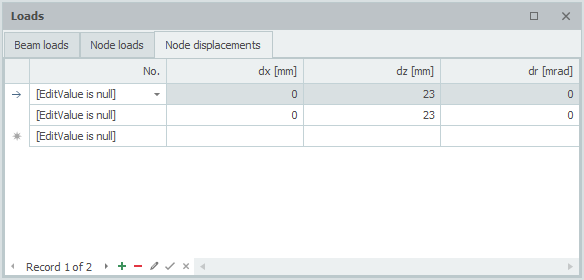
Table
Node displacements can also be added/changed in a table. It does not matter. It is also possible to change between graphical input and numerical input via tables.