XFrame2d Manual
| Copyright | Copyright © 2025 XFrame2d |
Introductie
XFrame2d is het gereedschap voor elke constructeur.
Met XFrame2d bepaalt u in een handomdraai en zeer eenvoudig de geometrisch lineaire of geometrisch niet-lineaire krachtsverdeling in uw constructie. Het programma is uiterst gebruiksvriendelijk, eigentijds en zeer snel.
XFrame2d kan optioneel worden uitgebreid met een volledig geintegreerde staalmodule waarmee de staalconstructie tevens wordt getoetst volgens EN1993.
Met XFrame2d produceert u een zeer uitgebreid en vooral leesbaar berekeningsrapport in RTF- of PDF-formaat. De uitvoer is volledig transparant.
Voor de staalmodule geldt dat alle gehanteerde formules volledig ingevuld worden weergegeven. Dit geeft u inzicht in de berekening en zal acceptatie van uw berekening door keurende instanties geen enkel probleem opleveren.
Wijzigingen
Wijzigingen t.o.v. versie 2.00
Nieuw in XFrame2d - Opleggingen onder een willekeurige hoek
Rol-oplegging onder een hoek / Verende oplegging onder een hoek
Alle mogelijke opleggingen
Er zijn zeer veel soorten opleggingen mogelijk. Vanzelfsprekend de bekende en standaard scharnieroplegging, roloplegging en momentvaste oplegging.
In XFrame2d kunt u echt willekeurig uw oplegging samenstellen. Verend in de x-richting en star opgelegd in de z-richting, of momentvast en in x-richting vrij, enz.
Ook opleggingen die vrij kunnen komen kunnen worden ingevoerd. Bijv. alleen een positieve reactiekracht. Ontstaat een negatieve reactie dan wordt de 'restrain' vrijgelaten en komt de oplegging vrij.
Nieuw in deze versie is dat u door gebruik te maken van een lokaal assenstelsel elke willekeurige oplegging onder een willekeurige hoek kunt plaatsen.
Nieuw in XFrame2d - Staalspanningscontrole volgens EN1993
Ook dit maakt XFrame2d uniek. De krachtsverdeling wordt gebaseerd op een geometrisch niet-lineaire krachtsverdeling waarbij tevens automatisch imperfecties in rekening worden gebracht. Dit is een zeer nauwkeurige rekenwijze en is toepasbaar voor elke constructie.
Uit de krachtsverdeling volgt rechtstreeks of de constructie gevoelig is voor 2de orde effecten (knik) of niet.
Staalmodule - Staalspanningscontrole volgens EN1993
De staaltoetsing wordt gebaseerd op een geometrisch niet-lineaire krachtsverdeling. (GNL)
Er hoeft geen rekening te worden gehouden met (vaak dubieuse) kniklengteberekeningen.
Automatische generatie en berekening van imperfecties (initiele scheefstand en initiele staaf vooruitbuigingen) voor elke belastingcombinatie door middel van equivalente horizontale belastingen volgens art 5.3.2 (7) - figuur 5.4. Vaak wordt dit vergeten!! Nu dus niet meer. U geeft alleen de belastingen op en de combinaties. Het programma bepaalt voor u per combinatie de equivalente horizontale belastingen en voegt die toe in de berekende belastingcombinatie.
Echt uniek - Geen 'black-box' berekening maar een heldere uitvoer met uitgeschreven EN1993 formules. De berekening is daarmee handmatig te controleren en geeft u meer inzicht in welke factoren maatgevend zijn.
Nieuw in XFrame2d - Plaatsen van een scharnier in een balk
Met een muisklik plaatst u een inwendig scharnier in een balk.
Inwendig scharnier
De staaf wordt automatisch opgedeeld en vanzelfsprekend ook de belasting(en). Op die manier kunt u gemakkelijk bijvoorbeeld een gerberligger ontwerpen.
Het scharnier verplaatsen kan natuurlijk ook en zeer eenvoudig. Dubbel-klikken op de knoop. Het dialoogvenster voor de knoop wordt geopend. Hier kunt u de x-coordinaat aanpassen.
Mogelijkheden en beperkingen
Mogelijkheden
-
Het programma bepaalt voor een tweedimensionale staafconstructie met gekozen stijfheden, de vervormingen en krachtsverdeling onder invloed van knoop- en/of staafbelastingen of voorgeschreven verplaatsingen.
-
De krachtsverdeling wordt bepaald volgens de verplaatsingsmethode, waarbij rekening wordt gehouden met normaal- en dwarskrachtvervorming.
-
Er kan gekozen worden voor lineaire krachtsverdeling (eerste orde) of geometrisch-niet-lineaire krachtsverdeling. (tweede orde)
-
Er zijn zeer veel soorten opleggingen mogelijk. Vanzelfsprekend de bekende en standaard scharnieroplegging, roloplegging en momentvaste oplegging.
-
In XFrame2d kunt u echt willekeurig uw oplegging samenstellen. Verend in de x-richting en star opgelegd in de z-richting, of momentvast en in x-richting vrij, enz. Ook opleggingen die vrij kunnen komen kunnen worden ingevoerd. Bijv. alleen een positieve reactiekracht. Ontstaat een negatieve reactie dan wordt de 'restrain' vrijgelaten en komt de oplegging vrij. Nieuw in deze versie is dat u door gebruik te maken van een lokaal assenstelsel elke willekeurige oplegging onder een willekeurige hoek kunt plaatsen.
-
Staven kunnen 'verend' (d.w.z. met rek- en/of rotatieveren) worden 'aangesloten' aan knopen.
-
Afhankelijk van gekozen run-optie kunnen in een bepaalde belastingscombinatie per staaf extreme momenten en vervormingen, of alle karakteristieken (dwarskracht, moment, hoekverdraaiing en vervorming) worden berekend.
-
Bij een geometrisch-niet-lineaire krachtsverdeling (tweede orde) kan worden gekozen voor een spanningsberekening volgens Eurocode 3: NEN-EN 1993-1-1.
Beperkingen
Hoewel het programma ruim van opzet is kent het voor de verschillende onderdelen de volgende beperkingen:
| Item | Limiet |
|---|---|
| Hoogste knoopnummer | 1000 |
| Hoogste staafnummer | 2000 |
| Hoogste profielnummer | 100 |
| Hoogste aansluitingsnummer | 100 |
| Aantal belastingsgevallen | 250 |
| Aantal belastingsgevallen per combinatie | 15 |
| Aantal belastingscombinaties | 250 |
Aanvullende beperkingen
-
Het programma is alleen geschikt voor prismatische staven. Een niet-prismatische staaf kan natuurlijk wel worden gesimuleerd door deze op te delen in een aantal staven met verlopende stijfheden.
-
Momentvaste aansluitingen (knoopverbindingen) kunnen uitsluitend lineaire verend worden voorgesteld. Een niet-lineaire (of tri-lineaire) voorstelling is vooralsnog niet mogelijk.
Tekenafspraak
Het programma kent drie rechtsdraaiend assenstelsels:
1. Hoofd-assenstelsel
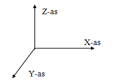
De ligging van dit globale assenstelsel is willekeurig. Het XY-vlak valt samen met het vlak van het raamwerk. Dit assenstelsel wordt gebruikt voor het vastleggen van knoopcoordinaten, knoopbeperkingen en knooppuntsbelastingen. Berekende knooppuntsvervormingen en oplegreacties worden ten opzichte van dit assenstelsel weergegeven.
2. Staaf-assenstelsel
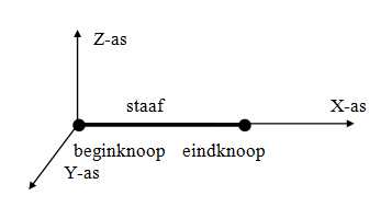
De oorsprong van dit assenstelsel ligt altijd in de beginknoop van betreffende staaf. Het XY-vlak valt samen met het vlak van het raamwerk. De X-as valt samen met de staafas.
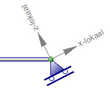
3. Knoop-assenstelsel
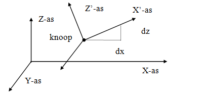
Er kan een lokaal (knoop-)assenstelsel worden opgegeven. De oorsprong ligt in de betreffende knoop. De richting van de X-as wordt bepaald door vanuit de knoop relatief een dx en dz op te geven. (zie bovenstaande figuur). Lokale assenstelsels kunnen worden gebruikt om knoopbeperkingen (opleggingen of 'restrains'), knoopbelastingen en/of knoopverplaatsingen in een willekeurige richting op te geven.
Tekenregels
De in- en uitvoergegevens worden ten opzichte van de hierboven beschreven assenstelsels weergegeven.
- Een kracht in de richting van de positieve X- of Z-as wordt als positief beschouwd.
- Een moment draaiend van de positieve X-as naar de positieve Z-as (volgens kurkentrekker-regel) is positief.
- Een moment tegengesteld aan de 'klokrichting' is positief.
Invoer
Snel aan de slag
Snel aan de slag met XFrame2d.
Deze handleiding beschrijft de user-interface van XFrame2d. Deze handleiding kunt u vanzelfsprekend raadplegen. Wilt u snel aan de slag zonder veel te hoeven lezen, bekijk dan de onderstaande korte demo's.
U zult ervaren hoe eenvoudig en ook hoe plezierig het is om met XFrame2d te werken.
Demo's
| Demo | Omschrijving |
|---|---|
| demo1 | Werken in het raster |
| demo2 | Werken met stramienen en niveaus. Invoeren van een simpel portaal. |
| demo3 | Werken met stramienen en niveaus. Invoeren van een 3-scharnierspant. |
| demo4 | Knopen en staven invoeren in een tabel |
| demo5 | Gebruik van zoom functie / Undo- en redo-functies |
| demo6 | Invoeren van een lokaal knoop-assenstelsel |
| demo7 | Inwendig scharnier in balk plaatsen - gerberligger |
| demo8 | Voorbeeld van een gedetailleerde uitvoer |
| demo9 | Voorbeeld van een vakwerkligger |
Approach
Working Method
XFrame2d allows you to work in multiple ways:
Graphical Input
You can draw your construction directly in the graphical screen using: - Node cursor for placing nodes - Beam cursor for drawing beams - Support cursors for adding supports - Load cursors for applying loads
Table Input
All elements can also be entered or modified through tables: - Nodes table - Beams table - Profiles table - Load cases table - Load combinations table
Combined Approach
The graphical and numerical input methods can be used simultaneously. After each change, all tables are updated and the construction is redrawn. The undo and redo functions work regardless of the input method used.
Workflow
- Define Geometry - Create nodes, beams, and supports
- Assign Profiles - Select steel or timber profiles for beams
- Apply Loads - Define load cases and load combinations
- Calculate - Run the analysis
- Review Results - View forces, moments, and deflections
- Optimize - Use the optimization tool for steel profiles
- Generate Output - Create PDF or RTF reports
Keyboard Shortcuts
General Shortcuts
| Shortcut | Action |
|---|---|
| Ctrl+N | New file |
| Ctrl+O | Open file |
| Ctrl+S | Save file |
| Ctrl+Z | Undo |
| Ctrl+Y | Redo |
| Ctrl+P | |
| F1 | Help |
| Escape | Cancel current operation |
View Shortcuts
| Shortcut | Action |
|---|---|
| Mouse wheel | Zoom in/out |
| Middle mouse button | Pan |
Selection
| Shortcut | Action |
|---|---|
| Ctrl+Click | Add to selection |
| Shift+Click | Add to selection |
| Left to right drag | Select window (fully contained) |
| Right to left drag | Select crossing (partially contained) |
Input Mode
While drawing beams or entering loads, you can type values directly on the keyboard to specify exact dimensions or magnitudes.
Geometrie
Grid Lines and Levels
Grid lines and levels are useful as reference lines. Nodes can easily be snapped to these lines.
Adding Grid Lines
Grid lines can be added in the table. The table consists of:
- Name - A description of the grid line
- Type - Vertical (grid line) or horizontal (level)
- Coordinate - The x-coordinate (for grid lines) or z-coordinate (for levels)
Using Grid Lines
When grid lines and levels are enabled in the Display Options, they appear as dotted lines in the graphical view.
With Snap Options configured to snap to grid lines, nodes will automatically snap to intersection points when placed near them.
Benefits
- Quick and accurate placement of nodes
- Consistent spacing in regular structures
- Visual reference for the construction layout
Knopen
Knopen
Knopen kunnen in het grafische scherm eenvoudig worden toegevoegd. Kies in de functiebalk voor  In deze modus kunt u meerdere knopen met behulp van de linker muisknop toevoegen. Bij plaatsing zit u rechtsonder in beeld de coordinaten.

Knopen kunnen willekeurig worden geplaatst, in een vast raster, of op stramienlijnen.
Opleggingen zijn knopen die in een bepaalde richting worden vastgezet.
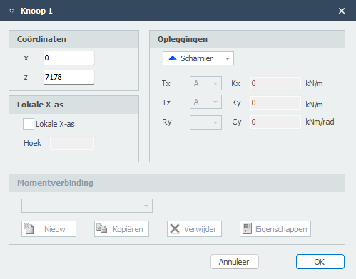
Wijzigen van een knoop
Wijziging van een knoop kunt u door met de linker muisknop op de knoop te klikken en vervolgens met de rechter muisknop te kiezen voor eigenschappen. Of nog makkelijker door te dubbel klikken op de knoop. Het onderstaande dialoogvenster wordt geopend:
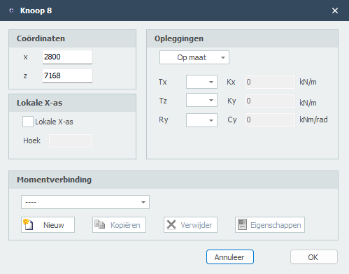
Coordinaten
x x-coordinaat
z z-coordinaat
Beperkingen
Zie Opleggingen
Lokale X-as
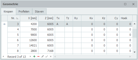
Tabel Knopen
Knopen kunnen ook in de tabel Knopen linksonder worden toegevoegd en/of gewijzigd. Het maakt niet uit. Ook kunt u tussentijds wisselen tussen grafische invoer en tabellarische invoer.
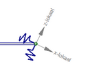
Lokaal assenstelsel
In elke knoop kan een (knoop-)assenstelsel worden toegepast.
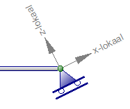
Voorbeeld van een rol-oplegging onder een hoek.
De oorsprong ligt in de betreffende knoop. De richting van de X-as wordt bepaald door vanuit de knoop relatief een dx en dz op te geven. (zie bovenstaande figuur). Lokale assenstelsels kunnen worden gebruikt om knoopbeperkingen (opleggingen of 'restrains'), maar ook om knoopbelastingen en/of knoopverplaatsingen in een willekeurige richting op te geven.
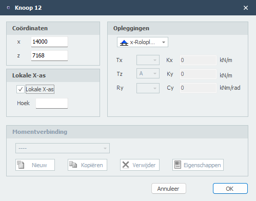
Lokale X-as
dx Relatieve afstand in x-richting
dz Relatieve afstand in z-richting
Met dx en dz wordt de ligging van de lokale x-as vastgelegd. De verhouding dx / dz bepaalt de hoek.
Opleggingen
Standaard opleggingen kunnen in het grafische scherm eenvoudig worden toegevoegd. Kies in de functiebalk voor een van de onderstaande opleggingen.
Opleggingstypen
 Scharnier
 Roloplegging z-richting
 Roloplegging x-richting
 Volledige inklemming
 Verende oplegging x-richting
 Verende oplegging z-richting
 Verende oplegging om y-as
In deze modus kunt u meerdere opleggingen met behulp van de linker muisknop toevoegen. Bij plaatsing zit u rechtsonder in beeld de coordinaten.
Opleggingen kunnen willekeurig worden geplaatst, in een vast raster, of op stramienlijnen.
Opleggingen zijn knopen die in een bepaalde richting worden vastgezet.
Wijzigen van een oplegging
Wijziging van een oplegging kunt u door met de linker muisknop op de knoop te klikken en vervolgens met de rechter muisknop te kiezen voor eigenschappen. Of nog makkelijker door te dubbel klikken op de knoop. Het onderstaande dialoogvenster wordt geopend:
Tabel Knopen
Opleggingen kunnen ook in de tabel Knopen linksonder worden toegevoegd en/of gewijzigd. Het maakt niet uit. Ook kunt u tussentijds wisselen tussen grafische invoer en tabellarische invoer.
Node Joints
Node joints (also called node connections) define how beams are connected at a node. By default, all beams meeting at a node are rigidly connected.
Types of Connections
- Rigid - Full moment transfer between beams
- Hinged - No moment transfer (pinned connection)
- Semi-rigid - Partial moment transfer using a rotation spring
Defining Node Joints
When multiple beams meet at a node, you can specify the connection type for each beam end:
- Select the node
- Open the properties dialog
- Set the connection type for each beam
Spring Connection
For semi-rigid connections, you can specify a rotation spring stiffness. This is useful for modeling:
- Flexible connections
- Partially restrained joints
- Specific joint behavior
See also: Spring Beam Connection
Joint in a Beam

An internal hinge (or joint) can be inserted within a beam to create a Gerber beam or other articulated structures.
Creating an Internal Hinge
- Select the internal hinge tool from the toolbar
- Click on a beam at the location where you want the hinge
- The beam is automatically split at that point with a hinge
Behavior
At an internal hinge:
- Moment is zero (no moment transfer)
- Shear force is continuous
- Normal force is continuous
- Rotation discontinuity is allowed
Use Cases
Internal hinges are commonly used for:
- Gerber beams (cantilever with suspended span)
- Three-hinged arches
- Articulated structures
- Modeling construction joints
Watch demo - Inserting an internal hinge
Verbindingen
Joints
In version 3.01 and later, XFrame2d includes a comprehensive steel joint module. Moment-fixed steel joints can be entered and their rigidity is automatically taken into account in the analysis.
Joint Types
The module supports various joint types according to Eurocode EN 1993-1-8:
- Beam-to-column joints
- Beam-to-beam joints
- Column bases
Joint Properties
For each joint, you can specify:
- Connection type
- Bolt configuration
- Plate dimensions
- Weld sizes
Rigidity
The joint rigidity is calculated according to the Eurocode component method. The calculated stiffness is then used in the structural analysis, providing more accurate results than assuming fully rigid or fully pinned connections.
Calculation
See Joints Calculation for details on how joint rigidity is determined.
Joints Calculation
The joint calculation in XFrame2d follows Eurocode EN 1993-1-8 using the component method.
Component Method
The component method analyzes a joint by:
- Identifying all active components (bolts, welds, plates, etc.)
- Calculating the stiffness of each component
- Assembling the overall joint stiffness
Calculated Properties
For each joint, the following are calculated:
- Moment resistance - Maximum moment the joint can transfer
- Rotational stiffness - Initial stiffness of the joint
- Classification - Rigid, semi-rigid, or nominally pinned
Integration with Analysis
The calculated joint stiffness is automatically used in the structural analysis. This provides:
- More realistic force distribution
- Better estimation of deflections
- Economical joint design
Output
The detailed joint calculation is included in the calculation report, showing all formulas and intermediate results according to the Eurocode.
Staven
Staven
In het grafische scherm kunnen staven eenvoudig worden toegevoegd door de staven te tekenen. Kies in de functiebalk voor  In deze modus kunt u 2 knopen selecteren waartussen de staaf zich bevindt.
- Kies de beginknoop met linker muisknop. Selecteer een bestaande knoop of plaats een nieuwe knoop.
- Kies de eindknoop met linker muisknop. Selecteer een bestaande knoop of plaats een nieuwe knoop.
Na selectie van de 2de knoop, de eindknoop verschijnt het onderstaande dialoogvenster.
Wijzigen van een staaf
Wijziging van een staaf kunt u door met de linker muisknop op de staaf te klikken en vervolgens met de rechter muisknop te kiezen voor eigenschappen. Of nog makkelijker door te dubbel klikken op de staaf. Het onderstaande dialoogvenster wordt geopend:
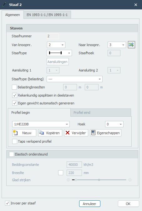
Staafnummer
Het staafnummer wordt automatisch gegenereerd.
Van knoopnr.
Het nummer van de beginknoop
Tot knoopnr.
Het nummer van de eindknoop
Staaftype
Door middel van het staaftype wordt opgegeven of de staaf in de betreffende knoop scharnierend of momentvast verbonden is aan deze knoop.
| Aanduiding | Omschrijving |
|---|---|
 |
beide zijden 'stijf' ingeklemd (default) |
 |
begin 'stijf' ingeklemd;eind scharnierend |
 |
begin scharnierend;eind 'stijf' ingeklemd |
 |
beide zijden scharnierend |
 |
beide zijden 'stijf' ingeklemd ALLEEN trek |
 |
begin 'stijf' ingeklemd;eind scharnierend ALLEEN trek |
 |
begin scharnierend;eind 'stijf' ingeklemd ALLEEN trek |
 |
beide zijden scharnierend ALLEEN trek |
 |
beide zijden 'stijf' ingeklemd ALLEEN druk |
 |
begin 'stijf' ingeklemd;eind scharnierend ALLEEN druk |
 |
begin scharnierend;eind 'stijf' ingeklemd ALLEEN druk |
 |
beide zijden scharnierend ALLEEN druk |
 |
beide zijden 'verend' ingeklemd |
 |
begin 'verend' ingeklemd;eind scharnierend |
 |
begin scharnierend;eind 'verend' ingeklemd |
 |
beide zijden scharnierend |

Specifiek en alleen voor de verende staafaansluitingen moeten de veergegevens worden opgegeven. Zie Verende staafaansluiting
EN 1993-1-1
Specifiek en alleen voor de toetsing volgens Eurocode 3: NEN-EN 1993-1-1 kunnen gegevens worden ingevoerd.
Kniklengte De kniklengte uit het vlak. De toetsing volgens Eurocode 3: NEN-EN 1993-1-1 is gebaseerd op een geometrisch niet lineaire krachtsverdeling. Dat betekent dat knik van de staven in het vlak van het raamwerken impliciet is voorzien. Per belastingcombinatie wordt iteratief inwendig evenwicht bepaald.
Knik uit het vlak van het raamwerk zal wel moeten worden beoordeeld. Default wordt de kniklengte uit het vlak gelijk genomen aan de staaflengte. In die gevallen dat dit afwijkt kan per staaf een afwijkende kniklengte worden ingevoerd.
Aantal kipsteunen Alleen relevant voor de toetsing van de kipstabiliteit: Het aantal kipsteunen is default 2. In die gevallen dat er meer dan 2 kipsteunen worden toegepast kan per staaf een afwijkend aantal worden ingevoerd.
Staafgroep Specifiek en alleen voor de toetsing van de kipstabiliteit kan een staafgroep worden ingevoerd. XFrame2d detecteert automatisch welke staven hiervoor in aanmerking komen. Alleen die staven die in het verlengde van de beschouwde staaf liggen, momentvast zijn verbonden en van hetzelfde profiel zijn, worden zichtbaar. U kunt aanvinken welke staven dat zijn.
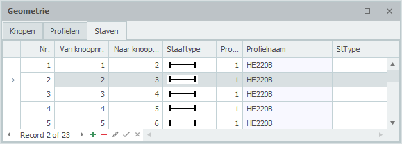
Tabel Staven
Staven kunnen ook in de tabel Staven linksonder worden toegevoegd en/of gewijzigd. Het maakt niet uit. Ook kunt u tussentijds wisselen tussen grafische invoer en tabellarische invoer.
Spring Beam Connection
Beams can be connected to nodes with springs instead of rigid connections. This allows modeling of:
- Flexible connections
- Partial moment transfer
- Semi-rigid joints
Types of Springs
Translation springs
- Spring in x-direction (axial)
- Spring in z-direction (transverse)
Rotation spring
- Spring for moment transfer
Setting Spring Stiffness
For each beam end, you can specify:
- Translation spring stiffness in x-direction (kN/m)
- Translation spring stiffness in z-direction (kN/m)
- Rotation spring stiffness (kNm/rad)
Special Cases
- Stiffness = 0 - Free (no force transfer)
- Stiffness = very high - Rigid connection
- Stiffness = calculated value - Semi-rigid behavior
Use Cases
Spring beam connections are useful for:
- Modeling actual joint flexibility
- Including connection stiffness from the Joints module
- Sensitivity analysis of connection behavior
Eurocode
XFrame2d includes integrated Eurocode design checks for both steel and timber structures.
Steel Design - EN 1993-1-1
For steel beams, the following checks are performed:
- Cross-section resistance (N, V, M)
- Buckling resistance
- Lateral-torsional buckling resistance
- Combined bending and compression
Timber Design - EN 1995-1-1
For timber beams, the following checks are performed:
- Bending stress
- Shear stress
- Compression/tension stress
- Combined stress
- Deflection limits
Analysis Method
XFrame2d uses geometric non-linear analysis (second-order analysis) for Eurocode checks. This approach:
- Automatically includes P-delta effects
- Accounts for initial imperfections
- Allows buckling length equal to system length
See Buckling for more details on the calculation approach.
Unity Checks
Results are displayed as unity checks (UC):
- UC < 1.0: Beam satisfies requirements

- UC > 1.0: Beam does not satisfy requirements

Double-click on the unity check indicator to see the detailed calculation.
Profielen
Steel Profiles
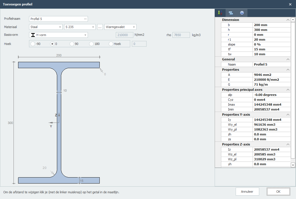
Profile Name
Description of profile.
Note: You can enter the standard profile name directly here as well. The program will look up the standard profile in the database. For example hea200 or HE200a.
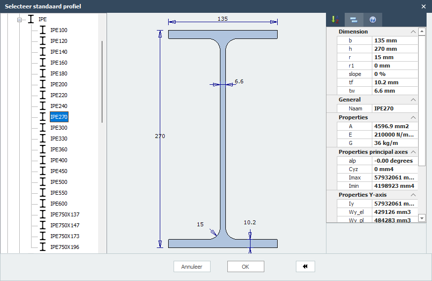
The module has an extensive library of standard profiles of more than 2700 profiles from which you can choose from. Click on the dots ... to open the profile browser.
Material
Name of material.
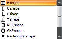
Basic Shape
There are a number of basic shapes available:
Note: You can change all dimensions by clicking on the number in the dimension line. This way you are able to enter any profile that is not in our database. This gives you flexibility.
E
The elasticity modulus.
Angle
Angle of profile in the y-z coordinate system.
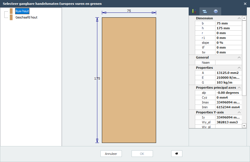
Timber Profiles
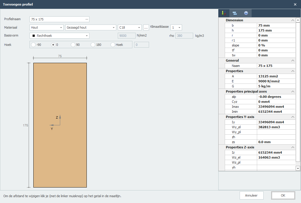
Profile Name
Description of profile.
Note: You can enter the standard profile name directly here as well. The program will look up the standard profile in the database. For example 85 x 175.
The module has an extensive library of standard profiles from which you can choose from. Click on the dots ... to open the profile browser.
Material
Name of material.
Type of Timber
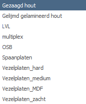
Select the timber type (softwood, hardwood, glulam, etc.)
Timber Class
C14, C16, C18, C20, etc.
Service Class
1, 2, or 3.
Basic Shape
There are a number of basic shapes available:
Note: You can change all dimensions by clicking on the number in the dimension line. This way you are able to enter any profile that is not in our database. This gives you flexibility.
E
The elasticity modulus.
Angle
Angle of profile in the y-z coordinate system.
Samengesteld profiel
Built-up Section
With this module you can build up any section by combining multiple profiles.
Features
- Combine standard profiles
- Add plates and custom shapes
- Create holes in sections
- Calculate combined section properties
Input Methods
- Table Input - Enter profiles numerically
- Graphical Input - Visual profile arrangement
Built-up Section Input
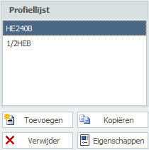
You can Add, Copy and Delete any profiles here. Using Properties you can change your profile or alter the profile dimensions.
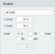
Profile Name
Enter the profile name or select from our profile database.
Special Input Syntax
1) Half H profile
Syntax: 1/2 profile name [ - min dimension ]
Example: 1/2IPE300 or 1/2HE650B-5
2) Rectangular plate
Syntax: S width x height or F width x height
Example: S200x12
3) Hole
Syntax: G width x height or H width x height
Example: H50x25
4) Round
Syntax: R diameter
Example: R50
5) Tube (segment)
Syntax: R diameter x thickness [ / angle1 / angle2 ]
Example: R500x12 or R500x12/0/180
6) Triangle
Syntax: D width x height or T width x height
Example: T50x60
U
Coordinate u in mm
V
Coordinate v in mm
Angle
Angle in degrees
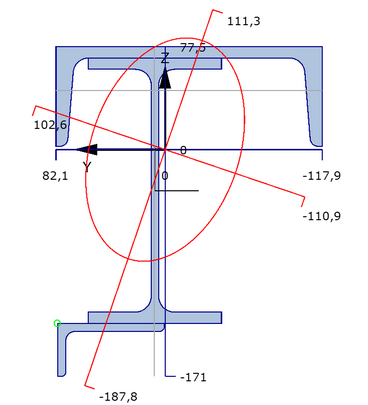
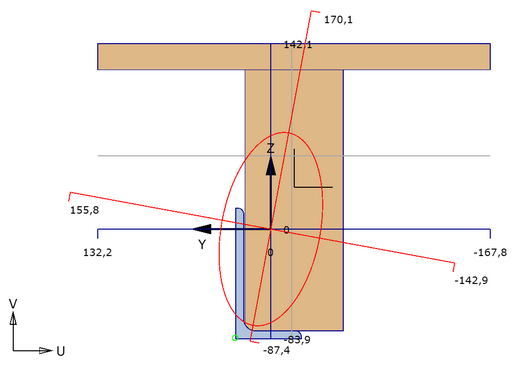
Graphical Input
Graphical view of the built-up section, with:
- Cross section of all profiles used. The focused section is displayed with another color.
- Coordinate system
- Centroid
- Principal axis
- Distances from centroid to all largest dimensions
- Display of radius of gyration
- Display of plastic neutral axis
Context Menu
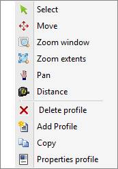
Right-click to access the context menu:
Menu Bar

Functions
Select You can change the focused profile by left-clicking within the profile bounds.
Move Profiles can be moved. There is an automatic snap to known points, which makes moving profiles quite easy. You can change the coordinates as well.
Zoom Window With this function you can zoom in on a part of your construction. You can use this to make the graphical input easier.
Zoom Extents With zoom extents the total built-up section is shown in full screen.
Pan By the use of pan you can drag/move a zoomed part of your drawing.
Distance In this mode distances can be measured.
Belastingen
Belastingsgevallen
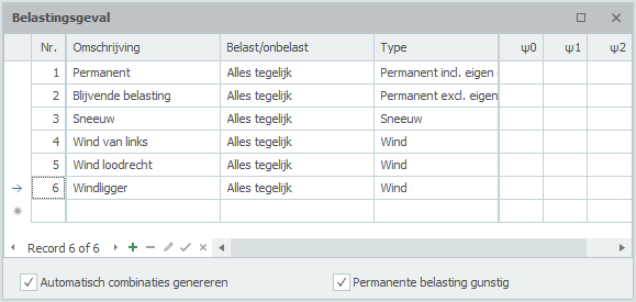
Belastingsgevallen
Invoeren van belastingsgevallen
Parameters
Nr. Dit nummer wordt automatische genereerd.
Omschrijving Vrij in te voeren omschrijving van het belastingsgeval.
Type Het type belasting (permanent of veranderlijk)
Standaard wordt er automatisch een belastingsgeval genereerd.
Sequence Load Cases
With a click on the right mouse button, the context menu shown below is opened. With these functions you can easily adapt the sequence of the load cases and/or insert load cases.
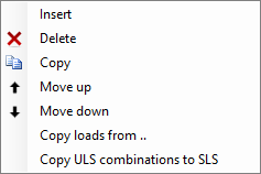
Insert
A new load case is created, and inserted above the current load case.
Delete
The load case is deleted, including all the loads.
Copy
The load case is copied, including all the loads.
Move Up / Move Down
A load case can be moved up and down a line.
Copy Load Case
With the right mouse button the following context menu is opened.
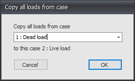
Copy Loads From...
Every load from an already existing load case can be copied. The dialog box shown below is opened. Herein you choose the load case from which you want to copy the loads.
Belastingcombinaties
Sequence Load Combinations
With the right mouse button the following context menu is opened. With these functions you can easily adapt the sequence of the load combinations, or insert new load combinations.
Insert
A new load combination is created and inserted above the current load case.
Delete
The load combination is deleted.
Copy
The load combination is copied.
Move Up / Move Down
A load combination can be moved up and down a line.
Copy ULS Combination to SLS
Every load combination of the type ULS will be copied as type SLS. The load factors are set to 1.
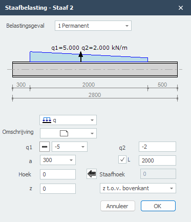
Staafbelastingen


Het onderstaande dialoogvenster wordt geopend.
Parameters
Belastingsgeval Keuze van het belastingsgeval. Hier kunt u ook direct een nieuw belastigsgeval aanmaken.
Type belasting
| Type | Omschrijving |
|---|---|
 |
gelijkmatig verdeelde belasting of verlopende belasting |
|
puntlast - F-belasting |
|
moment - M-belasting |
q1 De grootte van de belasting. Voor q-belasting de grootte van de belasting aan het begin in kN/m. Voor een puntlast de grootte van de belasting in kN, Voor een moment de grootte van de belasting in kNm.
Met  kunt het teken van de belasting eenvoudig veranderen.
q2 Alleen voor q-belasting de grootte van de belasting aan het eind kN/m.
a De afstand in mm waar de belasting begint, gerekend vanaf de beginknoop van de staaf.
b Alleen voor q-belasting de afstand in mm waar de belasting eindigt, gerekend vanaf de beginknoop van de staaf.
hoek Alleen voor de q- en F-belasting. De hoek in graden met de normaal. Tegengesteld aan de klokrichting is positief.
z De afstand in z-richting in mm t.o.v. de referentielijn. De referentielijn is instelbaar: 'z- t.o.v. bovenkant' / 'z- t.o.v. zwaartelijn' / 'z- t.o.v. onderkant'. Deze afstand is alleen relevant voor de toetsing van de kipstabiliteit.
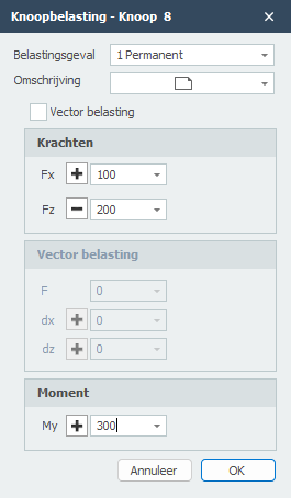
Knoopbelastingen

Het onderstaande dialoogvenster wordt geopend.
Parameters
Belastingsgeval Keuze van het belastingsgeval. Hier kunt u ook direct een nieuw belastigsgeval aanmaken.
Vector belasting Instelling of u de belasting als vector in een bepaalde richting wilt invoeren.
De knoopbelasting wordt standaard in het globale assenstelsel ingevoerd. Wanneer er voor de betreffende knoop een lokale assenstelsel is opgegeven dan worden de krachten t.o.v. van dit assenstelsel opgegeven.
Fx Grootte van de kracht in kN in x-richting
Fz Grootte van de kracht in kN in z-richting
My Grootte van het moment in kNm om y-as.
F Grootte van de kracht in kN
Knoopverplaatsingen
Het onderstaande dialoogvenster wordt geopend.
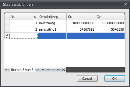
Hier kunt u de veerkarakteristieken van de verende aansluiting invoeren (bijvoorbeeld een semi-stijve momentverbinding).
Parameters
Nr. Het nummer van de aansluiting. Dit nummer wordt automatisch aangemaakt. Vanuit de staven wordt gerefereerd naar dit nummer. Op die manier kan dezelfde verbinding meerdere keren worden toegepast. De veerkarakteristieken worden eenmalig gedefinieerd. Achteraf bijstellen van de veerwaarden is dan ook zeer eenvoudig.
Omschrijving Vrij in te voeren tekst.
Kx De rekveerwaarde in N/mm
Cy De momentveerwaarde in Nm/rad
Bewerken
Make Selections
For selecting a (big) amount of nodes or beams in one time you can use the Select Window or Select Crossing.
This works exactly the same way as you might know from AutoCAD.
You draw a window from left to right. You draw a crossing from right to left.
Select Window (from left bottom to the right top)
- Determine, by the use of your mouse, the starting point of the window you want to draw. This is the left corner of the window you want to draw.
- Push the left mouse button.
- While you push the left mouse button you move the mouse to the right. A window is drawn in (partly transparent) blue.
- When you release the left mouse button, all the nodes and beams that are completely in this window will be selected.
Select Crossing (from the right top to the left bottom)
- Determine, by the use of your mouse, the starting point of the window you want to draw. This is the right corner of the window you want to draw.
- Push the left mouse button.
- While you push the left mouse button you move the mouse to the left. A window is drawn in (partly transparent) green.
- When you release the left mouse button, all the nodes and beams that are partially in this window will be selected.
Multi Select
To select multiple nodes or beams you can use the CTRL-button or the SHIFT-button.
By pushing the CTRL-button or the SHIFT button continuously, you 'draw' the selection window as described above.
Watch demo - Select window/crossing possibilities
Beeld
Display Options
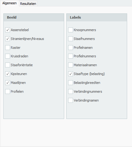
Geometry Options
Axis Draw the global coordinate system.
Grid Lines / Levels Grid lines, levels and/or help lines will be drawn dotted. See Grid Lines / Levels.
Regular Grid A regular grid is drawn. The size and the color of the regular grid are adaptable. See Regular Grid.
Crosshairs Two crosshairs are drawn (horizontal and vertical). This can come in handy when inserting nodes and beams.
Beam Orientation The local coordinate system (see Design Arrangement) will be drawn in the middle of the beam. The direction of the local z-axis is shown. This is important for inserting the beam loads which are entered in the local beam coordinate system. See Beam Loads.
Node Numbers Node numbers are shown between brackets (..) at the node.
Beam Numbers The beam numbers are shown between square brackets [..] at the beam.
Profile Names The profile names are shown at the beam.
Profile Numbers
Material Names
Results Options
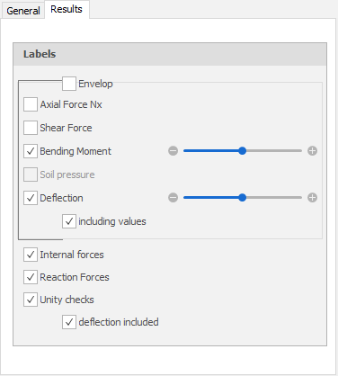
Axial Force Drawing of the N-line. The scale can be set.
Shear Force Drawing of the D-line. The scale can be set.
Bending Moment Drawing of the M-line. The scale can be set.
Soil Pressure For beams on an elastic foundation (Shallow foundation) the soil pressure can be displayed. The scale can be set.
Deflection Drawing of the deflection line. The scale can be set.
Internal Forces Drawing of the internal forces.
Reaction Forces Drawing of the reaction forces in all the supports.
Unity Checks
Per beam the unity checks can be displayed. These are results from the check according to the Eurocode (steel or timber). When the unity check is smaller than 1.00 the beam meets the criteria, and a green dot is drawn . When the unity check is bigger than 1.00 the beam does not meet the criteria and a red triangle is drawn.
When you double-click on the dot/triangle, a detailed calculation of the concerning beam is shown.
Dockable Windows
What are these? Dockable windows are windows that can be moved freely or placed on fixed spots (left/right/top/bottom of the screen).
Watch demo - Dockable windows possibilities
Available Tables
The tables for Geometry (Grid lines / Levels, Nodes, Profiles and Beams) and the tables for Loads (Load combinations, Beam loads, Node loads and Combinations) can be displayed or not.
Working with Tables
You can enter your construction fully graphically, whereby the use of tables is not really necessary. Nevertheless it can be handy to see, for instance, the node coordinates in tables. This is possible. But in contrary to many other programs you can also make any changes in these tables.
It does not matter. Graphical drawing or numerical input via tables can be done simultaneously. After each change, all tables are updated and the construction is redrawn. Of course the undo and redo functions still work.
Docking Options
The windows can be set as:
- Floating - In a random position but also outside the screen
- Docked - Left/right/top/bottom in the main screen
This gives you much freedom. You can decide for yourself what you find most pleasant. The program remembers this setting, so you only have to do this one time. Of course you can always change this.
Multi-Monitor Setup
For example, when you have two computer screens, you can show the construction graphically in full screen on one screen and show the tables on the other screen.
Changing Dimensions
Changing Dimensions or Values in the Graphical View
-
Move your cursor on the number in the dimension line.
-
When the dimension line gets its focus, the number is viewed bold. The color of the dimension changes from gray to black.
-
Press left mouse button. A dialog appears with the number to be edited.

-
Change the value.
-
Press
 . The dialog will be closed and the dimension has been changed.
or
Press  to cancel.
Load Generator
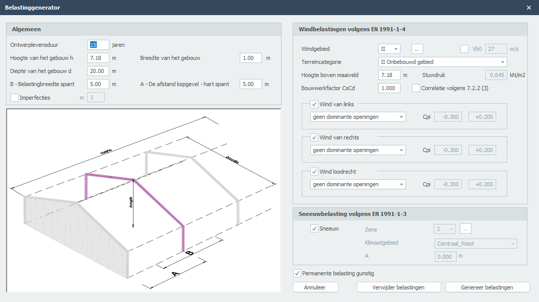
Working with the Load Generator
With the load generator you generate the snow and wind loads including all the load combinations in no time. Especially the wind loads according to the Eurocode are extensive and therefore laborious. The load generator will take this work out of your hands. The output specifically shows how the wind loads on the beams are determined and calculated.
Note! Before you can work with the load generator, you need to select the right beam type (load) per beam. You have the option between: floor, left vertical wall, right vertical wall, roof, overhang, wall/parapet. Based on this, the snow and wind loads are calculated. See Beams.
General
The dimensions of the building and the place of the central truss in the building.
Design Working Life The design working life of the building in years.
Height of the Building The height of the building in meters. This value is generated. The height and the depth of the building are the deciding factor for the wind pressure coefficients.
Depth of the Building The total depth of the building (measured perpendicular to the truss plane) in meters. The height and the depth of the building are the deciding factor for the wind pressure coefficients.
Width of the Building The total width of the building (measured in the truss plane) in meters. This value is generated. The height and the width of the building are the deciding factor for the wind thrust.
B - Load Width Truss The width (measured perpendicular to the truss plane) in meters that the truss needs to bear.
A - Distance End Wall to Center Truss The distance end wall - center truss (measured perpendicular to the truss plane) in meters. This distance is important for determining the wind pressure coefficients. An interpolation is executed between the wind pressure coefficients in different zones of the roof.
Snow Loads
Snow loads according to EN-1991-1-3 Select whether the snow load needs to be generated or not.
Wind Loads
Wind loads according to EN-1991-1-4
Wind Zone Dependent on the location of the structure, the wind zone is chosen. This value differs per country.
Terrain Category Based on local circumstances the terrain category is chosen.
Height Above Terrain The height of the building above terrain in meters.
Velocity Pressure Calculated velocity pressure.
Structural Factor Structural factor according to 6.3.
Correlation Setting if wind pressures on facades must be reduced by 0.85. E.g. according to Dutch NAD art. 7.2.2(3).
Wind from Left Select whether the wind has to be generated from left to right.
Wind from Right Select whether the wind has to be generated from right to left.
Wind Perpendicular Select whether the wind should be generated perpendicular (perpendicular to the truss plane).
The internal under- and over pressure is dependent on the size of the holes in the facades.
Generate Loads All the load cases and load combinations for snow and wind are created automatically. You can also change and extend these loads.
Resultaten
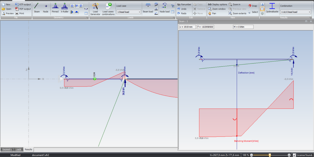
Spy

By the use of the spy you can look at the results of a certain beam in more detail.
Using the Spy
Push the button . The screen is now separated into two screens:
- Left screen - The total construction is shown, or a zoomed part of the construction
- Right screen - The selected beam is shown with beam forces
By moving the vertical splitter, the size of both screens can be adapted.
Viewing Results
In the left screen you click on one of the beams. This beam will be drawn in the right screen, including the beam forces. In the right screen you can move the vertical line. The forces are shown at the top of the right screen.
You have the option of: - N-lines (axial force) - D-lines (shear force) - M-lines (bending moment) - Deflection lines
By pushing the button one more time you will go back to just having one screen.
Calculation Settings

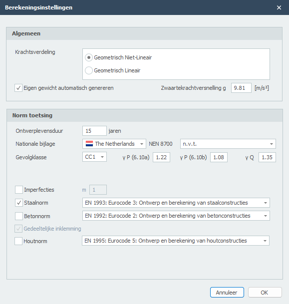
Analysis
You can choose between two sorts of analysis:
- Geometric Non-Linear (GNL) - Second-order analysis including P-delta effects
- Geometric Linear (GL) - First-order analysis
When you have chosen for a check according to the Eurocode (timber and steel), the analysis is always Geometric Non-Linear (GNL).
Dead Weight
You can choose if you want the dead weight to be automatically generated or not.
Gravity Acceleration g
Gravity acceleration in m/s².
Code Check
Design Working Life
The design working life of the construction in years.
Consequence Class
The consequence class of the construction. This determines among other things, the load factors that need to be used.
National Annex
The national annex can be chosen by country.
Steel Code
The steel code you want to use.
Imperfections
It can be set whether you want to take imperfections into account or not. For the time being, in XFrame2d global tilt is only possible in two directions. The beam imperfections (beam deformations) are not taken into account. However, the check according to Eurocode does take this into account, by assuming the buckling length equal to the beam length.
m
Relevant for steel structures only: This is the number of columns in a row including only those columns which carry a vertical load NEd not less than 50% of the average value of the column in the vertical plane considered.
Optimization

With the function optimization you can very easily and quickly create an optimal design of your steel construction. This function can save you a lot of steel kilograms.
How Does It Work?
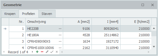
You will go through all the profiles (in the table Profiles) as you inserted before. See Beams.
The alternatives per profile will be shown directly. From these alternatives you can select another profile.
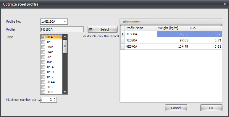
Profile No.
The profile number refers to the profile number in the table Profile shown below.
Profile
The chosen profile.
Type
Here you select the profile type (or group) in which there can be searched for alternative profiles.
Maximum Number per Type
Here you can enter the maximum amount of alternatives per profile type. Standard this value is at 3, but you can vary this value.
Select

Hereby you choose a profile from the right table 'Alternatives'. You can also double-click on the line in the table to choose the profile.
Alternatives
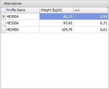
In this table the possible alternatives are directly shown. Normally the table is sorted on the unity check (u.c.). This unity check is the normative check according to the Eurocode EN1993.
It is also possible to sort the table by profile name or weight by clicking on the column text.
Remark: By changing the moment of inertia, the force distribution also changes. The optimization function does not take this into account. It could be possible that the new selected profiles will not be sufficient for your design and you have to use the optimization again. However, you will experience that the optimal design will be determined quickly and easily.
Menu
Instellingen
Drawing Settings
Tab Settings & Help > Settings > tab Drawing
Color Settings
Selected Profile Color setting of the selected (active) profile.
Beams Color setting of the beams.
Nodes Color setting of the nodes.
Supports Color setting of the supports.
Beam Load Color setting of the beam loads.
Node Load Color setting of the node loads.
Axis Color setting of the axis.
Background Color setting of the background. The background is drawn smoothly with two adjustable colors.
Snap Options
Tab Settings & Help > Settings > tab Snap Options
What is the Snap Option?
When, in the graphical screen, the cursor comes near a known point and/or an edge, the cursor is automatically placed to this point. There is been snapped to this point.
In many known design programs this functionality is used. It lets you select an exact point.
A very convenient functionality when drawing or displacing a node and/or a beam.
Settings
Snap Size The amplitude in mm in which is searched for a known point (node/middle of a beam/grid line). The default value is set to 150 mm. Generally this value suffices.
Snap to Node Setting whether there needs to be snapped to the nearest node.
Snap to Midpoint Setting whether there needs to be snapped to the midpoint of a beam. A red rectangle is displayed when this point is found.
Snap to Grid Lines/Levels Grid lines and levels can be used. Here you get to choose whether there needs to be snapped to the intersections. Nodes follow the grid lines and levels. The node will be drawn light grey and follows these lines. At the right bottom of the screen you can see the node coordinates. You can place a node graphically. Obviously you can also numerically change the exact node values afterwards. When you double-click on the node, a dialog box is opened. You can also change the node coordinates in this table. When you click on the node, the focus directly lies on the concerning line in the node table.
Snap to Existing Coordinate Lines All the nodes that are inserted are not directly visualized in the grid lines and levels. This makes snapping possible. This is a very useful functionality. Often the geometry of a construction is regular. Multiple nodes often lie on the same x- or z-coordinate. A construction can be inserted very easily and quickly.
Regular Grid
Tab Settings & Help > Settings > tab Regular Grid
Settings
Color Regular Grid A regular grid can be drawn onto the surface. The color is adjustable.
Minimum Grid Size Here the size of the surface can be set.
Grid Size The width (dx) and the height (dz) of the regular grid can be set.
Output Settings
Tab Settings & Help > Settings > tab Output
Settings
Drawing Setting whether the drawing of the construction should be in the output.
Drawing Size The height and the width on paper in mm.
- The height is limited to a maximum of 190 mm
- The width is limited to a maximum of 150 mm
User Defined Profiles
Tab Settings & Help > Settings > tab User Defined Profiles
Settings
Map Options for maps where the 'user defined profiles' are stored.
Preview
Menu: File > Preview
Toolbar: 
The dialog box of the print preview offers, next to the standard functionality, many extras including:
- Directly creating an e-mail with the calculation in PDF-format attached
- Generating a PDF-file
- Adding a watermark in the output file
Achtergrond
Buckling
XFrame2D has a fully integrated Eurocode EN 1993 steel and EN 1995 timber design module. Steel/timber test/design rules according to the newest/latest European standards. You are up-to-date with the latest standards. In XFrame2D all Eurocode design checks are based on a geometrically non-linear analysis. Imperfections (initial sway imperfections) will be automatically included in calculating load combination(s).
This is a very accurate calculation method and is applicable for every type of frame. Sway or braced/non-sway frames. Also, there is no need to calculate (error-prone) buckling lengths anymore. The geometrical non-linear analysis (Second-order analysis) ensures global buckling stability check.
The Way Steel Check According to the Eurocode is Implemented
Explanation
According to Eurocode EN 1993-1-1 art. 5.2.2 (7) a) no individual stability check for the members according to 6.3 is necessary if second order effects in individual members and relevant member imperfections (see 5.3.4) are totally accounted for in the global analysis of the structure. (Global initial sway imperfections and relatively initial local bow imperfections of members for flexural buckling).
In XFrame2d, the global initial sway imperfections according to art. 5.3.2 (3) a) are taken into account automatically. However, the relatively initial local bow imperfections of members for flexural buckling according to art. 5.3.2 (3) b) are not.
This means that the individual stability of the elements must be checked according to 6.3, whereby the buckling length may be set equal to the system length. According to art. 5.2.2 (7) b). By applying a geometric non-linear analysis, the moments and forces are of course including all second-order effects.
Advantages of This Approach
-
There is no need to calculate (error-prone) buckling lengths anymore. Buckling lengths are not calculated correctly in all cases and are certainly not load independent.
-
There is no need to make a choice for the type of framework, braced or non-sway. When the framework is sensitive to 2nd order, it follows directly from the analysis.
-
By global initial sway imperfections of the framework, the calculation process (the iteration) also works well with a symmetrical construction and symmetrical load.
-
Adjacent loads can easily be taken into account.
-
Lateral stability is also included in the stability check according to 6.3.3.
Tapered Beam
You can optionally enter a tapered beam. The tab "Profile end" is activated. Here you can enter the 2nd profile at the end of the bar.
Attention! The basic shape of the profile (H-, U-, L-shape, etc.) must match that of the profile at the beginning of the beam.
Force Distribution
For the mechanics calculation, the beam is automatically divided into a number of beam parts with a length corresponding to the average profile height. The profile section properties such as moment of inertia are calculated in the middle of each beam part. A constant moment of inertia is calculated for each beam part. Because the beam parts are quite short, this approach proves to be sufficiently accurate.
Stress Testing
For stress testing, the profile section properties are calculated per section (per x-distance). Thus, this calculation is exact.