Display Options
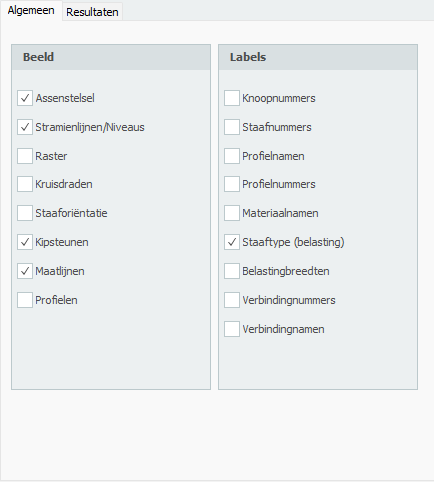
Geometry Options
Axis Draw the global coordinate system.
Grid Lines / Levels Grid lines, levels and/or help lines will be drawn dotted. See Grid Lines / Levels.
Regular Grid A regular grid is drawn. The size and the color of the regular grid are adaptable. See Regular Grid.
Crosshairs Two crosshairs are drawn (horizontal and vertical). This can come in handy when inserting nodes and beams.
Beam Orientation The local coordinate system (see Design Arrangement) will be drawn in the middle of the beam. The direction of the local z-axis is shown. This is important for inserting the beam loads which are entered in the local beam coordinate system. See Beam Loads.
Node Numbers Node numbers are shown between brackets (..) at the node.
Beam Numbers The beam numbers are shown between square brackets [..] at the beam.
Profile Names The profile names are shown at the beam.
Profile Numbers
Material Names
Results Options
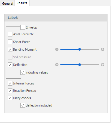
Axial Force Drawing of the N-line. The scale can be set.
Shear Force Drawing of the D-line. The scale can be set.
Bending Moment Drawing of the M-line. The scale can be set.
Soil Pressure For beams on an elastic foundation (Shallow foundation) the soil pressure can be displayed. The scale can be set.
Deflection Drawing of the deflection line. The scale can be set.
Internal Forces Drawing of the internal forces.
Reaction Forces Drawing of the reaction forces in all the supports.
Unity Checks
Per beam the unity checks can be displayed. These are results from the check according to the Eurocode (steel or timber). When the unity check is smaller than 1.00 the beam meets the criteria, and a green dot is drawn  . When the unity check is bigger than 1.00 the beam does not meet the criteria and a red triangle
  is drawn.
When you double-click on the dot/triangle, a detailed calculation of the concerning beam is shown.