Beam Loads


Beam loads are inserted in a local beam coordinate system. See Design Arrangement.
The dialog box shown below is opened.
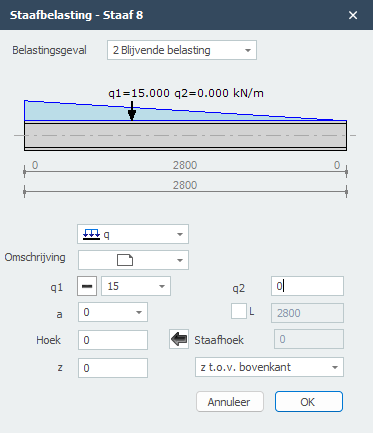
Load Case
Choice for the load case. Here you can directly insert a new load case.
Type of Load
Choose the type of load you want to add.
| Type | Icon | Description |
|---|---|---|
| q-load |  |
Even distributed load, or varying load |
| F-load | |
Point force |
| M-load | |
Moment |
Parameters
q1 The magnitude of the load. For the q-load: magnitude at the beginning in kN/m. For a point load: amplitude in kN. For a moment: magnitude in kNm.
With 
 you can change the sign of the loads very easily. Standard the sign is at because this is most common.
q2 Only for the q-load: the magnitude of the load at the end in kN/m.
a The distance in mm where the load starts, counted from the begin node of the beam.
L Only for the q-load: the length of the load. Standard the load goes up to the end of the beam.
Angle Only for the q- and F-load. The angle in degrees to the perpendicular. The direction opposite to the clockwise direction is positive.
Beam angle
The angle in degrees with the global x-axis. The direction opposite to the clockwise direction is positive. With  you can take over the angle from the previous section.
z The distance in the z-direction in mm relative to the reference line. The reference line is adjustable: 'z relative to top', 'z relative to centerline', 'z relative to bottom'. This distance is only relevant for lateral-torsional buckling resistance check.
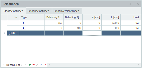
Table
Beam loads can also be added/changed in the table. It does not matter. It is also possible to change between graphical input and numerical input via tables.