Member Loads


The following dialog window opens.
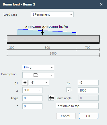
Parameters
Load case Selection of load case. Here you can also directly create a new load case.
Load type
| Type | Description |
|---|---|
 |
uniformly distributed load or varying load |
|
point load - F-load |
|
moment - M-load |
q1 The magnitude of the load. For q-load, the magnitude at the start in kN/m. For a point load, the magnitude in kN. For a moment, the magnitude in kNm.
With  you can easily change the sign of the load.
q2 Only for q-load, the magnitude at the end in kN/m.
a The distance in mm where the load starts, measured from the start node of the member.
b Only for q-load, the distance in mm where the load ends, measured from the start node of the member.
angle Only for q- and F-loads. The angle in degrees with the normal. Counter-clockwise is positive.
z The distance in z-direction in mm relative to the reference line. The reference line is adjustable: 'z- relative to top' / 'z- relative to centroid' / 'z- relative to bottom'. This distance is only relevant for lateral torsional buckling verification.